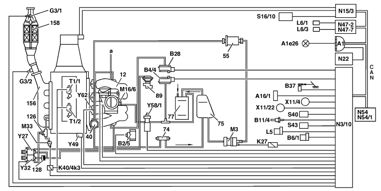

| GF07.61-P-0001-02GU | Fuel injection and ignition system motor electronics (ME-SFI) function diagram | Engine 111.974  |
 |
 |
| P07.61-0505-09 |
| 12 Intake manifold
40 Diaphragm pressure regulator 55 Fuel filter 74 Fuel cooler 75 Fuel tank 77 Activated charcoal filter 89 EGR valve 126 Secondary air injection shutoff valve (combination valve: check valve integrated) 128 Check valve (vacuum) 156 Exhaust manifold 158 Catalytic converter a Other consumers A1 Instrument cluster A1e26 CHECK ENGINE indicator lamp A16/1 Knock sensor B2/5 Hot film mass air flow sensor (intake air temperature sensor integrated) B4/4 Purge control monitoring pressure sensor up to 8/97 B6/1 Camshaft Hall sensor B11/4 Coolant temperature sensor B28 Pressure sensor |
B37 Pedal value sensor
G3/1 O2 sensor downstream of TWC G3/2 O2 sensor upstream of TWC (in exhaust pipe) K27 Fuel pump relay K40/4k3 Secondary air injection relay (integrated in fuse and relay module) L5 Crankshaft position sensor L6/1 Left front rpm sensor L6/3 Left rear rpm sensor M3 Fuel pump M16/6 Throttle valve actuator M33 Electric air pump N3/10 ME-SFI control module N15/3 ETC (electronic transmission control) control module N22 Automatic air conditioning (Auto A/C) pushbutton control module N47-2 ETS/SPS control module N47-7 ABS control module N54/1 Infrared drive authorization system control module N54 RCL (remote central locking) control module S16/10 Gear recognition switch |
S40 Cruise control switch V Decelerate/Set B Accelerate/Set SP Resume A Off S43 Oil level switch T1/1 Twin spark ignition coil 1, cylinders 1 and 4 T1/2 Twin spark ignition coil 2, cylinders 2 and 3 X11/4 Data link connector, 38-pin X11/22 Data link connector OBD II Y27 EGR switchover valve Y32 Air pump switchover valve Y49 Adjustable camshaft timing solenoid Y58/1 Purge control valve Y62 Fuel injectors CAN Data bus (Controller Area Network) Note: Model 129 as of 9/97 with leak test for purge control system (purge control system operational check discontinued) |