| GF42.31-P-4500-01A | BAS control module, function |  |
 |

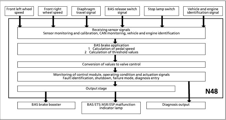
In all vehicles with engines 112, 113, 605, 606, 611, 612, 613 and ESP the BAS function is integrated in the ESP control module (N47-5). With models 163, 168, 203, 209, 215, 220 the BAS function is integrated in the ESP control module (N47-5). The BAS control module (N48) is divided up functionally as follows:  Signal conditioning Signal conditioning
 Logic section Logic section
 Safety circuit Safety circuit
Signal conditioning The following input signals are conditioned for the logic section:  2 rpm sensors at front (via CAN from traction system control module: ABS, ETS, ASR or ESP) 2 rpm sensors at front (via CAN from traction system control module: ABS, ETS, ASR or ESP)
 Stop lamp switch (via CAN from traction system control module: ABS, ETS, ASR or ESP) Stop lamp switch (via CAN from traction system control module: ABS, ETS, ASR or ESP)
 Vehicle identification (vehicle model and engine type via CAN from corresponding engine control unit) Vehicle identification (vehicle model and engine type via CAN from corresponding engine control unit)
 BAS diaphragm travel sensor BAS diaphragm travel sensor
 BAS release switch BAS release switch
|
Logic section
After the ignition is switched on, system initialization and safety checking is started. The system is enabled following a satisfactory check sequence. The conditioned input signals are processed in the logic section and the following values are calculated  Vehicle speed from the front wheel speed signals. Vehicle speed from the front wheel speed signals.
 Vehicle acceleration from several successive wheel speed measurements. Vehicle acceleration from several successive wheel speed measurements.
 The control module checks the voltage signal from the diaphragm travel sensor every 3 ms. The pedal speed is calculated from the voltage difference between two successive measurements. The control module checks the voltage signal from the diaphragm travel sensor every 3 ms. The pedal speed is calculated from the voltage difference between two successive measurements.
 Learning algorithm: calculation of vehicle deceleration for adaptation of triggering threshold to different braking system conditions. Learning algorithm: calculation of vehicle deceleration for adaptation of triggering threshold to different braking system conditions.
 Threshold: this is calculated from the basic threshold (vehicle identification values), vehicle speed, brake pedal speed and the values from the learning algorithm. Threshold: this is calculated from the basic threshold (vehicle identification values), vehicle speed, brake pedal speed and the values from the learning algorithm.
|
| If the calculated values exceed the specified threshold, BAS activation is initiated.
BAS activation is interrupted immediately following a signal from the BAS release switch Safety circuit The task of the safety circuit is to detect faulty signals in the control module and faults in the electrical cabling system. The following components are monitored continuously:  BAS solenoid valve (A7/7y1) BAS solenoid valve (A7/7y1)
 BAS diaphragm travel sensor (A7/7b1) BAS diaphragm travel sensor (A7/7b1)
 BAS release switch (A7/7s1) and BAS release switch (A7/7s1) and
 stop lamp switch (S9/1). stop lamp switch (S9/1). |
If a fault is detected, the system switches off. This is indicated to the driver by switching on the malfunction indicator lamp:
 BAS, BAS/ETS, BAS/ASR or BAS/ESP malfunction indicator lamp BAS, BAS/ETS, BAS/ASR or BAS/ESP malfunction indicator lamp
(A1e39, e49, e48 or e47).  In models 203, 209, 215, 220 via the multifunction display (A1p13). In models 203, 209, 215, 220 via the multifunction display (A1p13).
In addition, a fault code is stored in the control module. The safety circuit also constantly monitors the battery voltage. If the voltage falls below 10 V or exceeds 16-18 V, the system is also switched off until the voltage returns to the specified range. |