| GF42.45-P-0001B | Electronic stability program (ESP), function | 11.5.99 |
| |||||||||
 |
| The "Electronic Stability Program" (ESP) is an active safety system which improves vehicle stability in all driving situations.
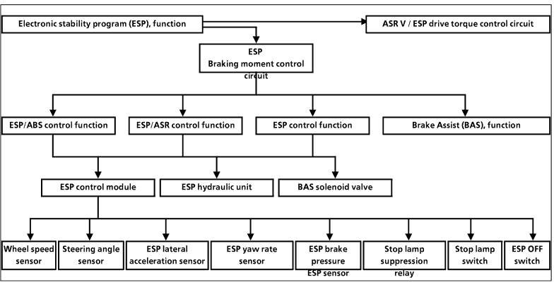
It functions by applying braking force to one or more wheels on the front or rear axle. ESP stabilizes the vehicle when cornering, braking, or during non-driven coasting to keep it on the road and in the desired lane. ESP complements the familiar functions of the anti-lock brake system (ABS), acceleration slip regulation (ASR) and engine braking regulation (EBR). The stability regulation function is superordinate to the ABS and ASR control systems. As well as actively intervening with the brakes, ESP also has an influence on engine / transmission management. The Electronic Stability Program (ESP) includes the following system interplay. ABS prevents the wheels from locking when the brakes are applied so that the vehicle remains steerable and stable as it decelerates. |
ASR prevents the powered wheels from spinning when the vehicle is being driven. It also improves directional stability and road adhesion and increases traction potential across the entire vehicle speed range.
EBR reduces brake slip at the drive wheels during deceleration and ensures directional control. ESP prevents the vehicle from breaking away when it is oversteered or understeered. In all situations it ensures that the vehicle does not deviate from the course specified by the driver (within the bounds of physical limits). Brake forces are produced selectively at the individual wheels to correct this. System interplay The engine electronics (ME) is used to adjust the drive torque. This system controls the engine by adjusting the position of the throttle valve and by altering the ignition timing. The gear setting is also evaluated by the electronic transmission control (EATC) to calculate the ESP drive torque control. |
The ABS and ASR functions are integrated in the ESP electronics of the brake control loop. In the following vehicles it also includes the BAS function (as of 3/99):
 Model 129 with engines 112, 113 Model 129 with engines 112, 113
 Model 202 with engines 111, 112, 113, 605, 611 Model 202 with engines 111, 112, 113, 605, 611
 Model 203 Model 203
 Model 210 with engines 112, 113, 605, 606, 611, 612, 613 Model 210 with engines 112, 113, 605, 606, 611, 612, 613
 Model 210 with engine 111 as of 08/99 Model 210 with engine 111 as of 08/99
 Model 170, 208, 215, 220 Model 170, 208, 215, 220
The basic ABS and ASR components are also combined in the ESP hydraulic unit. The function for the electronic gas pedal (EGP) and cruise control is contained in the engine control unit. Data is exchanged between the ESP control module, the engine control unit and (if fitted) with the transmission control module and BAS control module via a CAN data line. Advantages of ESP  Improves moving-off and acceleration capabilities by increasing traction; especially useful on road surfaces with different levels of grip and when cornering. Improves moving-off and acceleration capabilities by increasing traction; especially useful on road surfaces with different levels of grip and when cornering.
 Increases the level of active driving safety since only non-spinning wheels provide optimum traction without impairing side stability. Increases the level of active driving safety since only non-spinning wheels provide optimum traction without impairing side stability.
|
 Automatically adapts the engine torque to the respective wheel-to-road-surface traction possibilities if the driver accelerates too heavily. Automatically adapts the engine torque to the respective wheel-to-road-surface traction possibilities if the driver accelerates too heavily.
 Reduces the risk of skidding under all road conditions by automatically stabilizing the vehicle when braking, accelerating or coasting smoothly. Reduces the risk of skidding under all road conditions by automatically stabilizing the vehicle when braking, accelerating or coasting smoothly.
 Significantly improves the directional stability of the vehicle when cornering - up to the limit range. Significantly improves the directional stability of the vehicle when cornering - up to the limit range.
 Reduces the braking distance in corners or on roads with a smooth surface. Reduces the braking distance in corners or on roads with a smooth surface.
 A flashing warning lamp in the speedometer notifies the driver of ESP control and informs him that his vehicle is approaching the physical limits. A flashing warning lamp in the speedometer notifies the driver of ESP control and informs him that his vehicle is approaching the physical limits.
 The ESP or ASR can be deactivated via an ESP OFF switch. The deactivated status is indicated by a permanently lit warning lamp in the speedometer. Deactivation can help to improve traction ("cutting" effect) in deep snow or when snow chains are fitted. The ESP or ASR can be deactivated via an ESP OFF switch. The deactivated status is indicated by a permanently lit warning lamp in the speedometer. Deactivation can help to improve traction ("cutting" effect) in deep snow or when snow chains are fitted.
|
| Function overview
Essentially, all the forces acting on a vehicle from outside attempt to rotate the vehicle about its center of gravity, regardless of whether these are one-sided braking or drive forces or lateral forces. |
The Electronic Stability Program (ESP) analyzes the vehicle behavior and applies specific braking force to individual wheels to correct any instability. |
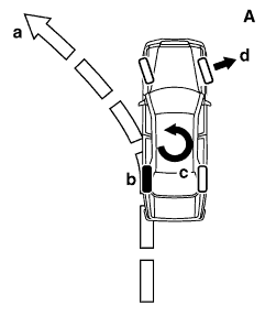
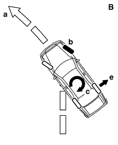
| Example A: Vehicle understeering (on left-hand bend)
The vehicle pushes outwards over the front wheels. Precisely calculated braking force is applied to the left rear wheel. Example B: Vehicle oversteering (on left-hand bend) The tail of the vehicle breaks away. Precisely calculated braking force is applied to the right front wheel. a Desired travel direction b Braked wheel c Generated compensating moment of vehicle d Understeering vehicle motion e Oversteering vehicle motion |
 |
 | ||
| P42.45-0203-02 | P42.45-0204-02 |
ESP operates:
 when cornering (vehicle under- or oversteered) when cornering (vehicle under- or oversteered)
 when driving straight ahead (vehicle deviates off course due to uneven road conditions) when driving straight ahead (vehicle deviates off course due to uneven road conditions)
To be able to perform these extremely precise control interventions, an expanded system of sensors is required compared with ASR. A distinction is made between: 1.) sensors which register driver requirements  Steering angle sensor Steering angle sensor
 Accelerator pedal position (throttle valve actuator) Accelerator pedal position (throttle valve actuator)
2.) sensors which measure the actual vehicle behavior  Yaw rate sensor Yaw rate sensor
 Lateral acceleration sensor Lateral acceleration sensor
 Brake pressure sensor Brake pressure sensor
 Wheel speed sensor Wheel speed sensor
The ESP control module (N47-5) records and processes the wheel speeds, the steering angle, the yaw rate of the vehicle, the lateral acceleration and the brake pressure at the front axle. The ESP control module (N47-5) is linked to the control modules of the engine/transmission management system over a CAN data bus. This digital link permits fast data exchange between the ESP control module, engine control unit, |
and transmission control module.
The ESP control module (N47-5) is continuously supplied with current data on engine torque, accelerator pedal position and transmission ratio. The forces attempting to rotate the vehicle about its center of gravity are detected via the yaw rate and lateral acceleration sensors. The longitudinal and lateral forces acting on the wheels can be calculated by this data acquisition. If these values exceed certain control thresholds, the appropriate solenoids as well as the high-pressure/return-flow pump in the hydraulic unit are actuated via the ESP control module (N47-5) in order to apply precisely defined brake pressure to one or more wheels. At the same time, commands are sent to the engine and transmission control module via the CAN data bus. Calculated values for throttle valve position and ignition timing are predefined and downshifting is suppressed in order to reduce driving torque. The precise and accurately proportioned intervention is completed within a few fractions of a second. Active brake intervention and driving torque reduction by the ESP ensure optimum vehicle stability. |
| The following control functions are performed during this process:
ESP braking moment control circuit ABS control If, for example, a wheel has a tendency to lock, the brake pressure in this wheel brake is regulated. The ESP hydraulic unit (A7/3) is actuated in three control phases (pressure build-up, pressure hold and pressure reduction) by the solenoids. ESP braking moment control circuit ASR control To brake the spinning wheel , the brake pressure is fed to the rear brake caliper via a pressure system in the hydraulic unit (pressure build-up). The other wheel can then transmit optimum driving power (locking differential effect). Solenoid valves in the ESP hydraulic unit (A7/3) regulate the braking torque with pressure build-up, pressure hold and pressure reduction phases. ESP drive torque control circuit ASR control In order to reduce an excessive drive torque and thereby obtain optimum traction, the drive torque is reduced over the CAN data bus between the ESP control module and the engine control module. |
The ESP control module continuously checks whether the control functions can be canceled owing to, for example, a sudden improvement in road grip so that the drive torque requested by the driver via the gas pedal can then be made available again.
ESP drive torque control circuit EBR control (except engines with fuel shutoff) If wheel slip at the drive wheels occurs when the gas pedal is released, this is also detected in the ESP control module. The signal is sent to the engine control module over the CAN data bus. On the basis of this information, the wheel slip is reduced by increasing the drive torque, and the side stability of the vehicle is thus increased. This process occurs without notifying the driver (ESP warning lamp). ESP brake moment and drive torque control circuit ESP control If over- or understeering is detected, calculated braking force is applied to the front or rear axle via the ESP control module and the hydraulic unit. This brake intervention counteracts the undesired driving behavior. A signal sent to the engine control unit via the CAN data bus triggers the demand-based reduction in drive torque by decreasing engine torque. |