GF54.00-P-0005F CAN data bus, function 11.7.96

MODEL  124 with ENGINES 104, 111, 119 (except 104.98)
MODEL  129 with ENGINES 104, 112, 113, 119, 120 (except 104.98)
MODEL  140 with ENGINES 104, 119, 120
MODEL  163 with ENGINE 112, 113
MODEL  168 with ENGINE 166
MODEL  170 with ENGINES 111, 112
MODEL  202 with ENGINES 104, 111, 112
MODEL  203 with ENGINE 111, 112
MODEL  208 with ENGINES 111, 112, 113
MODEL  210 with ENGINES 104, 112, 113, 119
MODEL  215 with ENGINE 113, 137
MODEL  220 with ENGINE 112, 113, 137
MODEL  230 with ENGINE 113


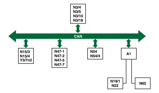
Example of engine CAN data bus
Models 129, 140, 163, 168, 170, 202, 203, 208, 210
TO1 Instrument cluster
N3/4 HFM-SFI [HFM] control module
N3/5 ECM control module up to 08/01
N3/10 ME-SFI [ME] control module
N3/18 ECM control module with throttle valve actuator as of 09/01
N15/3 ETC control module (in part Special Equipment)
N15/4 AKS control module (Special Equipment)
N19/1 Tempmatic air conditioning (TAC) pushbutton control module (in part Special Equipment)
cc Air conditioning (AAC) pushbutton control module (in part Special Equipment)
N47-1 ASR control module
N47-2 ETS control module
N47-5 ESP control module
N47-7 ABS control module
N54 RCL control module
N54/4 Radio frequency/infrared DAS [FBS] control module
N65 Cycling module Models 170, 210
Y3/7n2 Front-wheel-drive transmission control (FTC FGS) control module (Special Equipment)
 
    P54.18-2146-75

P07.61-2159-09

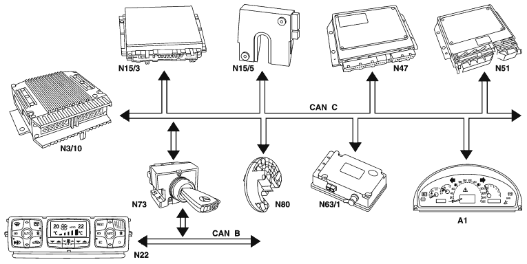
Example of engine CAN data bus, model 220 with engines 112, 113
TO1 Instrument cluster
N3/10 ME-SFI [ME] control module
N15/3 ETC (electronic transmission control) control module
N15/5 Electronic selector lever module control module
cc AAC pushbutton control module
N47 Traction system control module
  N51 AIRmatic with ADS control module
N63/1 Control module for DTR (SA)
N73 DI control module
N80 Steering column module

CAN B Engine CAN data bus
CAN C Body CAN data bus

Task
Data transfer between individual control modules
Readying sensor signals for several systems
Reducing the number of electric cables
Improving electromagnetic compatibility

Design
The CAN data bus consists of a special twisted two-core data line that connects all CAN users (control modules) in parallel. The two wires of the data line must not be mixed up (low or high level).
The engine control module and the RCL control module are always consumers with regard to bus adaptation. A 120 terminating resistor is therefore installed in the engine control module (except for the ME-SFI control module with engine 120, which is equipped with a 240 resistor). A 120 terminating resistor is installed in the DAS control module.

If the resistance of the CAN data line is measured (with the ignition switched off!) the various terminating resistors in the consumers are connected in parallel.
  Function
The data is transmitted digitally over the CAN data bus at various intervals. The individual data blocks are defined in a protocol and it is specified which data are received or transmitted by a control module.
Each connected control module is able to transmit or receive data.

The total of the data blocks, the short pause between two transmission intervals and further properties of the CAN data bus, are constantly checked. Any faults detected are stored.

Vehicles with electronic ignition switch control module (N73)
A distinction is made in the vehicle between the fast CAN engine data bus (CAN-C) and the slightly slower CAN body data bus (CAN-B). They are connected (via a gateway) in the electronic ignition switch control module (N73).


CAN data bus, see wiring diagrams.