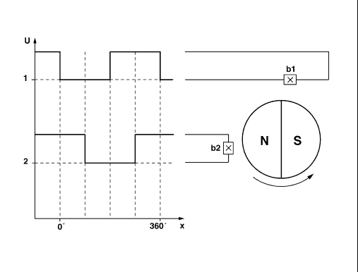
1 Square-wave pulses from Hall sensor b1
2 Square-wave pulses from Hall sensor b2
360° One rotation of motor shaft
b1,b2 Hall sensor
| GF72.29-P-4000A | Position recognition of power windows, function | 12.12.96 |
| |||
| Direction recognition
1 Square-wave pulses from Hall sensor b1 2 Square-wave pulses from Hall sensor b2 360° One rotation of motor shaft b1,b2 Hall sensor |
| |
| P72.29-0260-06 |
| Direction recognition
The two Hall sensors b1 and b2 are located at the shaft of the motor in the power window. They react to movements of the magnet. The Hall sensors supply one square-wave pulse for each rotation of the motor. The corresponding door control module (N69/1) or (N69/2), (MODELS 202/210 also N69/3 or N69/4), inputs the pulses from the Hall sensors. From the time difference between the pulses from Hall sensor b1 and the pulses from Hall sensor b2 the door control module determines the motor's direction of rotation. |
Position recognition
The corresponding door control module counts the pulses from the Hall sensors as a function of the determined rotational direction of the motor in the power window. The value in the position counter is increased when the window closes. In the other direction, the value in the position counter is reduced when the window opens. The zero position is defined as the upper lock-up point, i.e. when the window is completely open the counter should be at zero. The zero position is set by the normalization function. If the zero position is exceeded in the open direction, the count becomes negative. |
 |
Normalizing of power windows | GF72.29-P-4003A | |
| |
Lock-up recognition of power windows | GF72.29-P-4001A | |
| |
Door control module front driver side | GF72.29-P-4105A | |
| |
Door control module front passenger side | GF72.29-P-4106A | |
| |
Power windows in front doors | GF72.29-P-4101A | |
| |
Rear door control module | GF72.29-P-4102A |