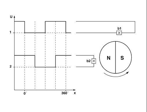
1 Square-wave pulses from Hall sensor b1
2 Square-wave pulses from Hall sensor b2
360° One rotation of motor shaft
b1 Hall sensor 1, SR (M12b1)
b2 Hall sensor 2, SR (M12b2)

| GF77.20-P-3001A | Sliding/pop-up roof position measurement, function | 23.1.97 |
| |||
| Direction recognition
1 Square-wave pulses from Hall sensor b1 2 Square-wave pulses from Hall sensor b2 360° One rotation of motor shaft b1 Hall sensor 1, SR (M12b1) b2 Hall sensor 2, SR (M12b2) |
 | |
| P72.29-0260-06 |
| Direction recognition
Hall sensor 1, SR (M12b1) and Hall sensor 2, SR (M12b2) are located at the shaft of SR motor (M12/1).These react to the movement of the magnet. They supply one square-wave pulse for each rotation of the motor shaft. The overhead control panel control module (N70) reads these Hall pulses. The overhead control panel control module (N70) recognizes the direction of rotation of the SR motor (M12m1) from the chronological offset of the Hall pulses from Hall sensor 1, SR (M12b1) and Hall sensor 2, SR (M12b2). |
Position measurement
The position counter in the overhead control panel control module (N70) counts the Hall pulses depending on the rotation direction of the SR motor (M12m1) recognized.The position counter is increased when the pop-up roof closes or the sliding roof opens. When the pop-up roof opens and the sliding roof closes the position counter is reduced. The zero position is defined as the pop-up roof open position, i.e. when the pop-up roof is fully opened the counter should be at zero. The zero position is set by the normalization function. If the zero position is exceeded in the open direction, the count becomes negative. |
| Sliding/pop-up roof, location/purpose/design/ | Model 202 as of 1.6.97 | GF77.20-P-4100A | |
| Synchronize sliding/pop-up roof, function | Model 202 as of 1.6.97 | GF77.20-P-3002A | |
| Overhead control panel control module, location/purpose/design/function | Model 202 as of 1.6.97 | GF82.20-P-4101A |