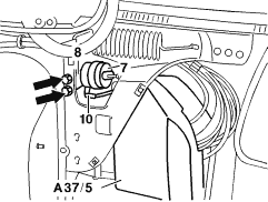
GF80.20-P-0005-01E | Central locking (CL), location of components |
Pneumatic control unit
Delivers the pressure or vacuum required for the following systems: ![]() ![]() ![]() |
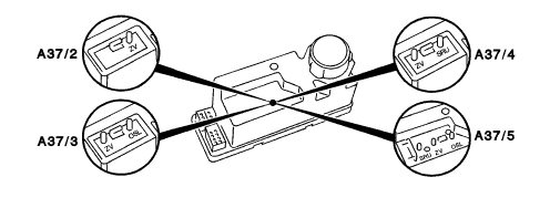
There are 4 different variants
![]() ![]() ![]() ![]() depending on the vehicle equipment used. |
A37/2 Pneumatic control unit, central locking (ZV)
A37/3 Pneumatic control unit, central locking (ZV), orthopaedic backrest/multi-contour backrest (OSL) A37/4 Pneumatic control unit, central locking (ZV), intake manifold vacuum increase (SRU) A37/5 Pneumatic control unit, central locking (ZV), orthopaedic backrest/multi-contour backrest (OSL), intake manifold vacuum (SRU) increase |
![]() | |
P80.20-0205-04 |
Note
As of 01/94, the pneumatic control unit has an electrical output for the function of the immobilizer (pin 7 on plug 1) for the ground |
actuation of the immobilizer relay (K38). |
Pressure cut-off point for central locking system | (mbar) | > 450 |
---|---|---|
Pressure cut-off point for orthopaedic seat backrest/multi-contour backrest | (mbar) | 550-620 |
Switching time of central locking system | (s) | approx. 1 |
Safety switching time in the event of leaks in the central locking system | (s) | 10 ± 1 |
Safety switching time in the event of leaks in the auxiliary appliances SRU or OSL | (s) | approx. 60 |
Power consumption | (A) | max. 10 |
Closed-circuit current draw terminal 30 | (mA) | < 1 |
Closed-circuit current draw terminal 15 (auxiliary appliances) | (mA) | < 50 |
Door actuators
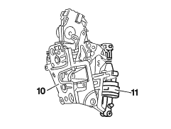
The central locking system actuators of the front and rear doors are attached and screwed on directly at the door locks. The control rods are integrated in the central locking system actuators and are clipped into the door locks. Adjustment is not required. Arrangement (right is mirror image) 10 Left front door lock 11 Central locking system actuator |
![]() | |
P80.20-0206-01 |
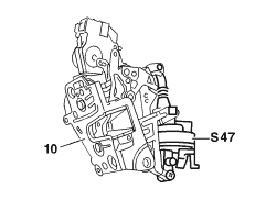
On vehicles with anti-theft warning system (EDW) a door actuator (S47) with an electrical switch is attached to the door lock of the left front door (10). | ![]() | |
P80.20-0207-01 |
Trunk lid actuator
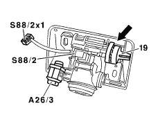
The trunk lid pneumatic actuator (19) is attached directly to the trunk lid lock in a similar way to the 140 model range. Adjustment is not required. |
![]() | |
P80.20-0208-01 |
Tank flap actuator
Clip-type pneumatic actuator with direct locking linkage, anti-theft locking device and emergency release button. The central locking system actuator (7) is pushed onto a bracket (8). |
![]() | |
P80.20-0209-01 |
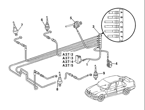
Pneumatic lines with quick-fit plug connection
The pneumatic lines have a plug at their ends which engages in the pneumatic connection bush of the actuators. The pneumatic lines to the door actuators run to the actuators from the distributor plug on the pneumatic control unit (A37/2 - A37/5) via the door contact places. The pneumatic lines to the tank flap actuator and trunk lid actuator run directly to the actuators from the distributor plug on the pneumatic control unit (A37/2 - A37/5). Note As of 12/93, pneumatic line sets will be used which are produced by means of a new manufacturing process, the so-called crimp-on technique. |
The pneumatic distributors which were previously mounted on the pneumatic control unit will not be used anymore.
A pneumatic line mounted on the pneumatic control unit leads to a 6-way distributor to distribute the bi-pressure of the central locking system. A separate pneumatic line runs to each of the central locking system actuators from this 6-way distributor. Letters on the distributor indicate to which central locking system actuator the pneumatic line leads. A. Driver door, left D. Rear door, right B. Driver door, right E. Filler neck flap C. Rear door, left F. Trunk lid |
Pneumatic line set for central locking system as of 12/93 | ![]() | |
P80.20-0210-06 |