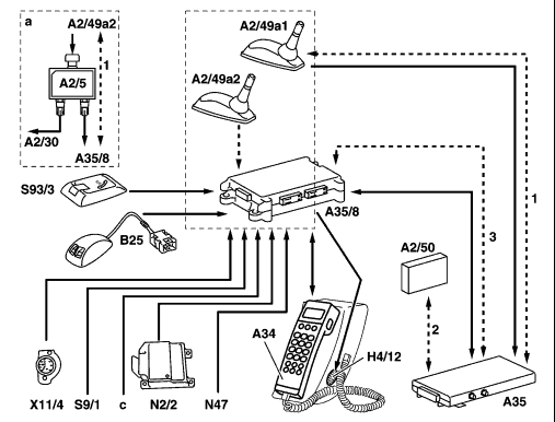
| GF82.95-P-0003-02A | Emergency call (E-call) system, block diagram |  |
| 1 Connection to CTEL antenna
2 Connection to substitute TELE AID antenna (A2/50) 3 Connection to active antenna (illustrated with A2/49a1 or A2/50) A2/5 Antenna splitter A2/30 APS navigation processor A2/49a1 CTEL antenna except models 129, 215  on model 129 rod antenna A28 on model 129 rod antenna A28
on model 215 CTEL antenna A2/22 A2/49a2 GPS antenna except models 129, 215  on models 129, 215 GPS antenna A2/23 on models 129, 215 GPS antenna A2/23
A2/50 Substitute EMERGENCY CALL antenna A34 CTEL handset A35 CTEL transmitter and receiver A35/8 EMERGENCY CALL control module B25 Hands-free system microphone H4/12 Hands-free system speaker N2/2 Emergency tensioning retractor with airbag (AB), except model 215 |
 | |
| P82.95-2052-06 |
 on model 215 N2/2 is replaced by on model 215 N2/2 is replaced by
N2/7 Restraint systems control module N47 Traction systems control module, receives signal by front left wheel speed sensor, L6/1 S9/1 Stop lamp switch |
S93/3 EMERGENCY CALL pushbutton switch
X11/4 Data link connector a Only on vehicles with auto-pilot system (APS) c Back-up signal |