GF83.20-P-2003E Heater circuit, function 26.1.98

MODEL  202


Illustrated on engine 111

1 Coolant expansion reservoir
1a Silica gel reservoir
2 Radiator
3 Thermostat (position with engine at operating temperature)
4 Coolant pump
6 Heater core
7 Vent line for coolant expansion reservoir
8 Thermovalve

M13 Coolant circulation pump
Y21 Duovalve
Y21y1 Left duovalve
Y21y2 Right due valve


M Engine
S Washing water reservoir, heated by coolant
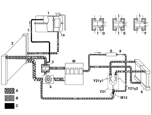
 
    P83.20-2050-06

A Coolant return
B Coolant feed
C Vent line to coolant expansion reservoir
D Short circuit mode, temperature < 87°C (coolant flows through engine and passenger compartment heater)

  E Mixing phase, temperature > 87 °C and < 102 °C (thermostat opens, coolant starts to flow)
F Cooling mode temperature > 102 °C (thermostat open, all coolant flows through radiator)

Function
The coolant pump (4) pumps coolant through the engine (M). There the coolant absorbs heat from the engine, heating up the coolant. Then the heated coolant flows through the heater core (6) where the heat is transferred to the air in the passenger compartment. The coolant flowing through the heater core (6) is controlled by the duovalves (Y21y1 and Y21y2) located in the coolant return (A). The coolant can be controlled separately for the left and right sides.
 
The coolant returns to the coolant pump (4) via the coolant return (A). A coolant circulation pump (M13) can be installed between the duovalve (Y21) and the coolant pump (4). The major portion of the coolant flows from the engine (M) to the coolant thermostat (3) instead of flowing through the heater. The thermostat routes the water through the radiator (2) or directly to the coolant pump (4) depending on the temperature.