GF80.20-P-0005E | Central locking (CL), function | 20.7.94 |
|
General
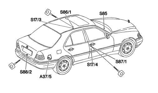
Version 1 up to 11/94, ![]() ![]() A37/5 Pneumatic system equipment (PSE) control module S17/3 Left front door contact switch S17/4 Right front door contact switch S85 Interior CL control switch S86/1 Left front lock switch (convenience) S87/1 Right front lock switch (convenience) S88/2 Trunk lid lock switch (convenience) |
![]() | |
P80.20-0204-05 |
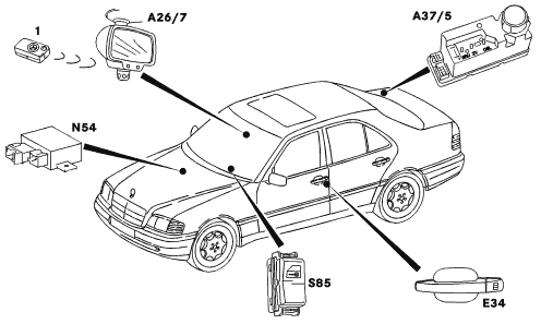
Version 2 as of 12/94, except ![]() ![]() 1 Transmitter key A26/7 RCL [IFZ] receiver (interior rear view mirror) A37/5 Pneumatic system equipment (PSE) control module E34 RCL [IFZ] function indicator N54 RCL [IFZ] control module S85 Interior CL control switch |
![]() | |
P80.20-0270-05 |
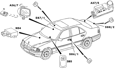
Version 3 ![]() ![]() 1 Transmitter key A26/7 RCL [IFZ] receiver (interior rear view mirror) A37/5 Pneumatic system equipment (PSE) control module N54 RCL [IFZ] control module S85 Interior CL control switch S86/1 Left front lock switch (convenience) S87/1 Right front lock switch (convenience) S88/2 Trunk lid lock switch (convenience) |
![]() | |
P80.20-0271-05 |
The vehicle can be locked or unlocked centrally from the driver or passenger door or from the trunk lid by actuating the key. Moreover, the central locking can be locked or unlocked with the interior CL control switch (S85) when the vehicle has been unlocked previously from the outside.When one of the front doors is opened the vehicle is unlocked centrally if it was locked previously with the interior CL control switch.All doors, the trunk lid and the tank flap are included in the central locking. | Notes
On vehicles with infrared remote control for central locking as of 01/94 the CL, ATA and CF can no longer be controlled with the mechanical switch (except ![]() ![]() For the immobilizer function stage 1 from 01/94 to 11/94 the PSE control module (A37) has an electrical output (pin 7 on connector 1) for control of the starter lockout relay (K38). |
Function
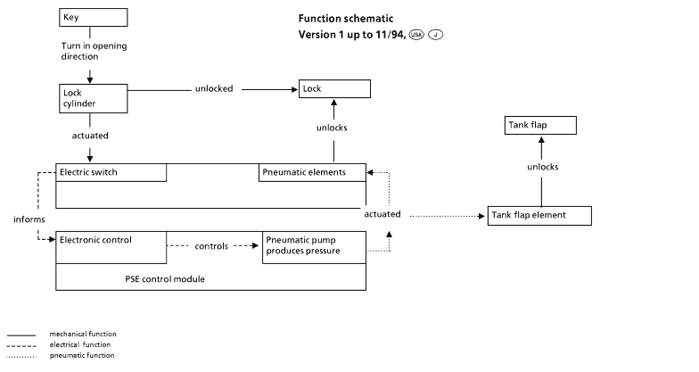
Version 1 up to 11/94, ![]() ![]() Function sequence using unlocking vehicle from the driver's door as an example When the key in the lock cylinder is turned to the left the electric switch (SN1) in the lock is switched.This switch then conducts negative voltage over its control lead to the pneumatic control module. The PSE control module (A37) starts up and generates a vacuum in the line system to all pneumatic elements.The diaphragms in the elements are pressed up actuating the locks over a linkage and unlocking them. The tank flap element unlocks the flap directly When a pressure of approx. 450 mbar is reached in the system, a pressure switch switches off the supply pump. |
The pressure in the pneumatic line system and the elements is released by the PSE control module (A37) - the system is no longer under pressure and the unlocking operation is completed.
The locking operation is accomplished analog to the unlocking operation.However, a second electric switch (SN2) in the lock is switched by turning the key to the right. This switch then conducts ground via its control lead to the PSE control module (A37). The direction of rotation of the pump motor is reversed by reversing the polarity producing the vacuum required for locking. |
Function
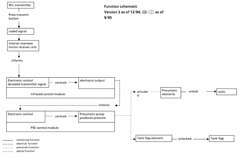
Version 2 as of 12/94, ![]() ![]() Function sequence using unlocking vehicle with infrared remote control for central locking (RCL) Point the transmitter output on the remote control at the receiver in the interior rearview mirror and press the transmit button.The infrared remote control then conducts negative voltage via its control lead to the PSE control module. The PSE control module (A37) starts running and produces a pressure which is conducted through a system of lines to all pneumatic elements.The diaphragms in the elements are pressed up actuating the locks over a linkage and unlocking them. The tank flap element unlocks the flap directly When a pressure of approx. 450 mbar is reached in the system, a pressure switch switches off the supply pump. The pressure in the pneumatic line system and the elements is released by the PSE control module (A37) - the system is no longer under pressure and the unlocking operation is completed. |
The locking operation is accomplished analog to the unlocking operation. However, the next time the transmit button is pressed the PSE control module (A37) is also actuated with ground over the second control lead of the infrared remote control module. The direction of rotation of the pump motor is reversed by reversing the polarity producing the vacuum required for locking. |
![]() |
![]() |
Central locking (CL) operation | GF80.20-P-0005-09E | ||
Central locking (CL), location of components | GF80.20-P-0005-01E |